Yottacontrol produces a wide range of I / O modules, the models with RS485 serial connection support the Modbus RTU protocol, the models with ethernet and WiFi support the Modbus TCP protocol. These modules allow you to distribute I / O within a structure by connecting to the existing Ethernet or WiFi network, in this article an example of management with our programmable modules.
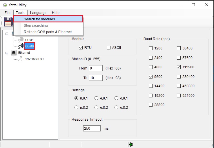
Connecting the module to the USB port of the PC Windows recognizes the module and automatically installs the management driver, it is seen as an additional COM port (COM8 in the example). It is also possible to connect it via an RS485 serial port, if the PC does not have a serial port it is possible to use our USB / Serial converters.

Scan devices
From the Yotta Utility program, select the COM port the device is connected to, if Ethernet or WiFi devices you can select the Ethernet port. By running the scan, the program will display the list of connected devices. The Ethernet/WiFi devices are configured by default in DHCP so there must be an active DHCP server in the network.
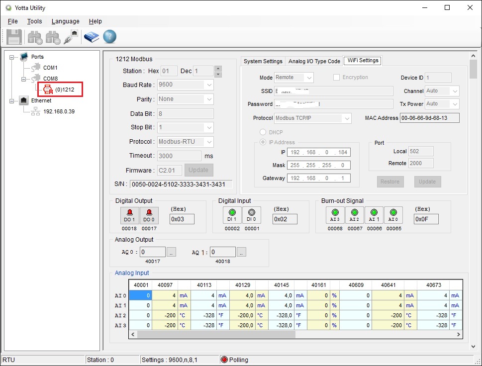
By selecting the module you can see its status. From the various windows it is possible to carry out the configuration. For configuration, position the selector located on the base of the product on Init before switching on the module.
System configuration
In the window System Settings it is possible to define the Modbus serial communication parameters, the status to which the outputs must return when switched on or when there is no communication.
Field Timeout settings allows you to set the Modbus communication control time, if the module does not receive Modbus commands after the defined time, it forces the outputs in the way set in the field Comm. Fail Safe. Confirm the settings by pressing the button Update.

Ethernet modules configuration
In the window Ethernet Settings it is possible to define the parameters for the connection to the ethernet network, the field Auto reconnect allows you to set the socket auto-connection time if there is no communication. Confirm the settings by pressing the key Update.
The module supports up to 7 simultaneous TCP connections on the defined Modbus port, and 1 HTTP connection on port 80. It is important to set the Auto reconnect not too long to prevent the socket from getting stuck in case of connection errors. I recommend setting a time slightly higher than the time for the client to send Modbus packets.

Browser access
The modules of the A-18xx series have an active web server on port 80. Typing the IP address of the module from the browser displays the information. The figure to the side shows the status of an A-1860 module with 8 digital inputs and 4 digital outputs.
Through the program Yotta Utility in addition to configuring the module, it allows you to define the Verified Code access and assign a text to each I/O of the module. In the field Verified Code it is necessary to set the password which enables the setting of the outputs on the module (Default 88888888).

WiFi modules configuration
The WiFi modules can be configured both in Access point mode (Mode AP) what station (Mode Remote). In the window WiFi Settings you can define the parameters for the WiFi network. Confirm the settings by pressing the button Update. If the SSID or network password has a space use the $. Example, "my pass word" becomes "my $ pass $ word".
If connected in Modbus TCP / IP and the connection is interrupted (the WiFi gateway is switched off or the client is switched off) the module keeps the connection active for 300 seconds (5 minutes) during which it is not possible to open other connections on the configured port.
WiFi AP or station mode
Mode AP: The module assumes the IP address 192.168.1.1/24 and activates the DHCP server. Once the setting is complete, turn off the module, set the selector on the base to “Normal” and turn the module back on. After the initialization time, the module will generate the network with the defined SSID and it will be possible to connect.
Mode Remote: Once the settings have been completed, turn off the module, set the selector on the base to “Normal” and turn the module back on. After the initialization time, the module will connect to the WiFi network and it will be possible to verify the connection simply by performing a ping of the assigned IP address.