Pulse-width modulation (or PWM, short for Pulse Width Modulation), is a modulation that allows to obtain an average value depending on the ratio between the duration of the positive and negative impulse (duty cycle).
This function block manages the hardware PWM circuit present on some modules (Can only be used on modules that have hardware PWM management), is not to be confused with the FB PWMOut, PWM output management which instead creates a software PWM (Much less performing in frequency) but which can be used with any logic output. To enable the optional outputs, the protection code must be requested, see function and function block protection. However, it is possible to use them freely in test mode for 15 min.
The FB allows the definition of the frequency value Frequency and duty cycle Duty of the PWM generator on the indicated module and channel. The range of values depends on the module used and in general we will have.
- Frequency:=0, the PWM generator ends the current period and resets the output.
- Duty:=0, the PWM generator ends the current period and deactivates the output.
- Duty:=100, the PWM generator ends the current period and activates the output.
- Duty:=50, the PWM generator tries to keep the duty cycle at 50% at all frequency values, generator frequency.
Modules with PWM output
This FB operates only on modules that implement PWM hardware management, below a summary table.
| Module code | PWM channels | Footnotes |
|---|---|---|
| MPS050-PCB131 | 1 | OUT0, frequency range 5Hz÷3kHz |
| MPS053-PCB135 | 1 | OUT0, frequency range 5Hz÷3kHz |
| MPS054-PCB137 | 2 | OUT0÷1, frequency range 5Hz÷3kHz |
| MPS056-PCB141 | 2 | OUT0÷1, frequency range 5Hz÷3kHz |
| PCB124 * 010 | 4 (including 3 option) | OUT0÷3, frequency range 8Hz÷5kHz |
Duty cycle setting
The modules have opto-isolated outputs therefore delays are generated on the rising and falling edges which, as the frequency increases, reduce the settable range of the duty cycle. Because of the delays as the frequency increases, the granularity of the frequency and duty settings increases.
| Module code | duty min | duty max | Duty Min (20Hz) | Duty Max (20Hz) |
|---|---|---|---|---|
| MPS054-PCB137, MPS056-PCB141 | 1% | 100-(Freq/27.2) | 1% | 100-(20/27.2)=99% |
| PCB124 * 010 | Freq/71.4 | 99% | 20 / 71.4 =1% | 99% |
Function lock
CODESYS: Not available
LogicLab: eLLabXUnified12Lib
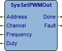
Description
Address (USINT) It is necessary to specify the module address on which to perform the PWM management (Range from 0 to 15). The value 0 indicates the first extension module, 1 the second and so on. The value 255 indicates the CPU module.
Channel (USINT) The channel address must be specified on the module (Range 0 to 15).
Frequency (REAL) Output frequency value (Refer to the manual of the card used). The value is expressed in Hz.
Duty (REAL) Duty cycle value of the output signal, set to 50 if used as a frequency generator. The value is expressed in %.
Done (BOOL) PWM generator correctly set.
Fault (BOOL) Error in execution
Examples
How to use the examples.
ST_SysSetPWMOut: Channel 0 (Out 00) of the CPU module is set to generate a 100Hz PWM signal with 50% duty cycle.
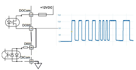
ST_PWMOutPulsesCount: Using a counter connected to the PWM output it is possible to block or modify the output frequency after a pre-set number of pulses. As can be seen from the diagram, the DO00 output of the PWM is connected to the Di00 input of the counter.
4 pulses at 100Hz are generated, followed by 3 pulses at 200Hz and finally 2 pulses at 50Hz then the output resets to zero, simulating the command of stepping, starting, forwarding, slowing down and stopping motors. The reading of the counter must be performed within the duration of 1 pulse (at 200Hz every 5mS) therefore the program must be executed in Fast task.
LogicLab (Ptp116, ST_SysSetPWMOut)
PROGRAM ST_SysSetPWMOut
VAR
    PWMOut : SysSetPWMOut; (* PWM output *)
END_VAR

// *****************************************************************************
// PROGRAM "ST_SysSetPWMOut"
// *****************************************************************************
// This program presets the PWM output channel 0 on CPU module.
// -----------------------------------------------------------------------------

    // -------------------------------------------------------------------------
    // PWM OUTPUT
    // -------------------------------------------------------------------------
    // Preset PWM output.

    IF (SysFirstLoop) THEN
        PWMOut.Address:=255; //Module address
        PWMOut.Channel:=0; //Module channel
        PWMOut.Frequency:=100.0; //Frequency output (Hz)
        PWMOut.Duty:=50.0; //Duty cycle (%)
    END_IF;

    // Manage the PWM output.

    PWMOut(); //PWM output

// [End of file]
LogicLab (Ptp116, ST_PWMOutPulsesCount)
PROGRAM ST_PWMOutPulsesCount
VAR
    Start : BOOL; (* Start command *)
    CaseNr : USINT; (* Program case *)
    PulsesThr : UDINT; (* Pulses threshold *)
    PulsesCtr : UDINT; (* Pulses counter *)
    PWMOut : SysSetPWMOut; (* PWM output *)
    CInp : SysGetCounter; (* Counter acquisition *)
END_VAR

// *****************************************************************************
// PROGRAM "ST_PWMOutPulsesCount"
// *****************************************************************************
// This program shows how to use a counter to count the PWM output pulses. After
// a defined number of pulses the output frequency is changed some times.
// -----------------------------------------------------------------------------

    // -------------------------------------------------------------------------
    // PROGRAM INIT
    // -------------------------------------------------------------------------
    // Executed at first program execution, all variables are initialized.

    IF (SysFirstLoop) THEN
        PWMOut.Address:=255; //Module address
        PWMOut.Channel:=0; //Module channel

        CInp.Address:=255; //Module address
        CInp.Channel:=0; //Module channel
        CInp.Mode:=16#00000000; //Acquisition mode
    END_IF;

    // -------------------------------------------------------------------------
    // PWM OUTPUT
    // -------------------------------------------------------------------------
    // Preset PWM output.

    CASE (CaseNr) OF

        // ---------------------------------------------------------------------
        // Wait for the start command.

        0:
        IF NOT(Start) THEN RETURN; END_IF;
        Start:=FALSE; //Start command

        // Set ouput frequency, duty cycle and save counter value.

        CInp(); //Counter acquisition
        PWMOut(Frequency:=100.0, Duty:=50.0); //PWM output
        PulsesThr:=CInp.Value; //Pulses threshold
        CaseNr:=CaseNr+1; //Program case

        // ---------------------------------------------------------------------
        // Wait for the defined number of pulses (4 pulses at 100 Hz).

        1:
        CInp(); //Counter acquisition
        PulsesCtr:=CInp.Value-PulsesThr; //Pulses counter
        IF (PulsesCtr < 4) THEN RETURN; END_IF;

        // Set ouput frequency, duty cycle and save counter value.

        PWMOut(Frequency:=200.0, Duty:=50.0); //PWM output
        PulsesThr:=CInp.Value; //Pulses threshold
        CaseNr:=CaseNr+1; //Program case

        // ---------------------------------------------------------------------
        // Wait for the defined number of pulses (3 pulses at 200 Hz).

        2:
        CInp(); //Counter acquisition
        PulsesCtr:=CInp.Value-PulsesThr; //Pulses counter
        IF (PulsesCtr < 3) THEN RETURN; END_IF;

        // Set ouput frequency, duty cycle and save counter value.

        PWMOut(Frequency:=50.0, Duty:=50.0); //PWM output
        PulsesThr:=CInp.Value; //Pulses threshold
        CaseNr:=CaseNr+1; //Program case

        // ---------------------------------------------------------------------
        // Wait for the defined number of pulses (2 pulses at 50 Hz).

        3:
        CInp(); //Counter acquisition
        PulsesCtr:=CInp.Value-PulsesThr; //Pulses counter
        IF (PulsesCtr < 2) THEN RETURN; END_IF;

        // Stop PWM output with signal low.

        PWMOut(Frequency:=0.0, Duty:=0.0); //PWM output
        CaseNr:=0; //Program case
    END_CASE;

// [End of file]