Lo scopo di questo articolo è quello di dimostrare come utilizzando i ns sistemi SlimLine (Anche in versione OEM) sia possibile ingegnerizzare sistemi custom abbinando moduli commerciali dotati di interfaccia I2C. Su Internet troverete una infinità di moduli per le più svariate necessità a costi relativamente bassi, molti di questi prodotti vengono pubblicizzati per interfacciamento con Arduino o Raspberry.
Utilizzando la funzione SysI2CWrRd è possibile collegare al bus di espansione dei ns sistemi SlimLine qualsiasi dispositivo con interfaccia I2C, SlimLine provvede anche a generare i 5Vdc di alimentazione del dispositivo. Vediamo come collegando all’interfaccia parallela del modulo LCD QC2004A (Basato su controller Hitachi HD44780U) una scheda interfaccia I2C sia possibile gestire un display da 4 righe da 20 caratteri.
Function block “I2CLCDDisplay”
Questo blocco funzione gestisce una scheda I2C di interfaccia display che si basa sull’integrato PCF8574P, un’espansione di I/O a 8 bit su bus I2C. L’alimentazione è da 3 a 5V e l’indirizzo I2C impostato è 16#3F. Sulla scheda troviamo
- Un indicatore LED.
- Un potenziometro per il controllo del contrasto.
- Un ponticello per l’abilitazione al comando della retroilluminazione.
- Ponticelli per la configurazione indirizzo sul bus I2C.
Per il passaggio dei dati da visualizzare sul display si utilizza il buffer DData dichiarato come array di 4 stringhe da 20 caratteri.
La gestione è suddivisa in sequenze, non potendo acquisire il segnale di display occupato, viene effettuata una temporizzazione tra le varie sequenze superiore al tempo necessario al display per eseguire il comando più lungo.
La scheda interfaccia gestisce solo 4 bit del bus quindi tutti i comandi sono suddivisi su due nibbles da 4 bits ciascuno. Per eseguire la scrittura del dato a 8 bits sul display è stato definito il metodo WrDisplay.
LogicLab (Mdp238, I2CLCDDisplay)
FUNCTION_BLOCK I2CLCDDisplay
VAR
    CaseNr : USINT; (* Case gestione *)
    DDIDx : USINT; (* Display data index *)
    TimeBf : UDINT; (* Time buffer (uS) *)
END_VAR

VAR_INPUT
    Enable : BOOL; (* FB enable *)
    Backlight : BOOL; (* Backlight command *)
    I2CAddress : USINT; (* LCD I2C address *)
    DData : ARRAY[0..3] OF STRING[ 20 ]; (* Display data *)
END_VAR

VAR_OUTPUT
    Fault : BOOL; (* FB fault *)
    ErrorNr : UDINT; (* Error number *)
END_VAR

// *****************************************************************************
// FUNCTION BLOCK "I2CLCDDisplay"
// *****************************************************************************
// Questo blocco funzione esegue la gestione del controller display SainSmart
// IIC/I2C/TWI 1602 Serial LCD Module Display For Arduino UNO MEGA R3.
// Il controller utilizza un PCF8574 "Remote 8-bit I/O expander for I2C-bus" per
// gestire i segnali di controllo di un display con interfaccia parallela tipo
// QC2004A Systronix basato sul controller HD44780U della Hitachi.
// -----------------------------------------------------------------------------
// Gli 8 ports di uscita del I/O expander sono connessi al display nel modo.
//
// Pin4 P0 -> Pin 4 Rs Display
// Pin5 P1 -> Pin 5 R/W Display
// Pin6 P2 -> Pin 6 En Display
// Pin7 P3 -> Comando backlight
// Pin9 P4 -> Pin 11 D4 Display
// Pin 10 P5 -> Pin 12 D5 Display
// Pin 11 P6 -> Pin 13 D6 Display
// Pin 12 P7 -> Pin 14 D7 Display
// -----------------------------------------------------------------------------

    // -------------------------------------------------------------------------
    // INIZIALIZZAZIONI
    // -------------------------------------------------------------------------
    // Eseguo reset bit di one shot.

    IF (Fault) THEN Fault:=FALSE; CaseNr:=0; END_IF;

    // Gestione errore esecuzione.

    //IF (ErrorNr <> 0) THEN ErrorNr:=0; Fault:=TRUE; RETURN; END_IF;

    // -------------------------------------------------------------------------
    // GESTIONE ABILITAZIONE
    // -------------------------------------------------------------------------
    // Gestione abilitazione blocco funzione.

    IF NOT(Enable) THEN CaseNr:=0; RETURN; END_IF;

    // -------------------------------------------------------------------------
    // TEMPORIZZAZIONE TRA CASES PROGRAMMA
    // -------------------------------------------------------------------------
    // Siccome non è possibile leggere dal display il segnale di busy, viene
    // eseguita una temporizzazione tra i vari cases pari al tempo necessario
    // al display per eseguire il comando più lento (Clear display 760 uS).

    IF ((SysTimeGetUs()-TimeBf) < 1000) THEN RETURN; END_IF;
    TimeBf:=SysTimeGetUs(); //Time buffer (uS)

    // -------------------------------------------------------------------------
    // GESTIONE CASE PROGRAMMA
    // -------------------------------------------------------------------------
    // Eseguo gestione case LCD.

    CASE (CaseNr) OF

        // ---------------------------------------------------------------------
        // INIZIALIZZAZIONE DISPLAY
        // ---------------------------------------------------------------------
        // In questi cases, viene eseguita la sequenza di reset del display.
        // In tutti questa cases occorre eseguire l'interfacciamento a 4 bit,
        // al termine della fase sarà possibile accedere al display ad 8 bit
        // eseguendo due accessi consecutivi a 4 bit.
        // ---------------------------------------------------------------------
        // Eseguo comando "Default function set".

        0, 1, 2:
        IF NOT(SysI2CWrRd(I2CAddress, 3, ADR('$30$34$30'), 0, 0)) THEN ErrorNr:=10; RETURN; END_IF;
        CaseNr:=CaseNr+1; //Case gestione

        // ---------------------------------------------------------------------
        // Eseguo set interfaccia a 4 bit. Dopo questo comando è possibile
        // inviare comandi ad 8 bit eseguendo due accessi consecutivi a 4 bit.

        3:
        IF NOT(SysI2CWrRd(I2CAddress, 3, ADR('$20$24$20'), 0, 0)) THEN ErrorNr:=20; RETURN; END_IF;
        CaseNr:=10; //Case gestione

        // ---------------------------------------------------------------------
        // INIZIALIZZAZIONE DISPLAY
        // ---------------------------------------------------------------------
        // Eseguo comando "Function set DL, N, F", 8 bits, 2 lines, 5*7 dots

        10:
        IF NOT(THIS.WrDisplay(FALSE, 16#28)) THEN ErrorNr:=30; RETURN; END_IF;
        CaseNr:=CaseNr+1; //Case gestione

        // ---------------------------------------------------------------------
        // Eseguo comando "Display on/off control".

        11:
        IF NOT(THIS.WrDisplay(FALSE, 16#04)) THEN ErrorNr:=31; RETURN; END_IF;
        CaseNr:=CaseNr+1; //Case gestione

        // ---------------------------------------------------------------------
        // Eseguo comando "Clear display".

        12:
        IF NOT(THIS.WrDisplay(FALSE, 16#01)) THEN ErrorNr:=32; RETURN; END_IF;
        CaseNr:=CaseNr+1; //Case gestione

        // ---------------------------------------------------------------------
        // Eseguo comando "Cursor and display shift".

        13:
        IF NOT(THIS.WrDisplay(FALSE, 16#06)) THEN ErrorNr:=33; RETURN; END_IF;
        CaseNr:=CaseNr+1; //Case gestione

        // ---------------------------------------------------------------------
        // Eseguo comando "Display on/off control".

        14:
        IF NOT(THIS.WrDisplay(FALSE, 16#0C)) THEN ErrorNr:=34; RETURN; END_IF;
        CaseNr:=100; //Case gestione

        // ---------------------------------------------------------------------
        // SCRITTURA DATI SU DISPLAY
        // ---------------------------------------------------------------------

        // ----------------------------------------------------------[1a Riga]--
        // Eseguo comando "Set DDRAM address".

        100:
        DDIDx:=0; //Display data index
        IF NOT(THIS.WrDisplay(FALSE, 16#80)) THEN ErrorNr:=50; RETURN; END_IF;
        CaseNr:=CaseNr+1; //Case gestione

        // ---------------------------------------------------------------------

        101:
        IF NOT(THIS.WrDisplay(TRUE, eGetBYTE(ADR(DData[0])+DDIDx))) THEN ErrorNr:=51; RETURN; END_IF;
        DDIDx:=DDIDx+1; //Display data index
        IF (DDIDx >= 20) THEN CaseNr:=110; END_IF;

        // ----------------------------------------------------------[2a Riga]--
        // Eseguo comando "Set DDRAM address".

        110:
        DDIDx:=0; //Display data index
        IF NOT(THIS.WrDisplay(FALSE, 16#C0)) THEN ErrorNr:=52; RETURN; END_IF;
        CaseNr:=CaseNr+1; //Case gestione

        // ---------------------------------------------------------------------

        111:
        IF NOT(THIS.WrDisplay(TRUE, eGetBYTE(ADR(DData[1])+DDIDx))) THEN ErrorNr:=53; RETURN; END_IF;
        DDIDx:=DDIDx+1; //Display data index
        IF (DDIDx >= 20) THEN CaseNr:=120; END_IF;

        // ----------------------------------------------------------[3a Riga]--
        // Eseguo comando "Set DDRAM address".

        120:
        DDIDx:=0; //Display data index
        IF NOT(THIS.WrDisplay(FALSE, 16#94)) THEN ErrorNr:=54; RETURN; END_IF;
        CaseNr:=CaseNr+1; //Case gestione

        // ---------------------------------------------------------------------

        121:
        IF NOT(THIS.WrDisplay(TRUE, eGetBYTE(ADR(DData[2])+DDIDx))) THEN ErrorNr:=55; RETURN; END_IF;
        DDIDx:=DDIDx+1; //Display data index
        IF (DDIDx >= 20) THEN CaseNr:=130; END_IF;

        // ----------------------------------------------------------[4a Riga]--
        // Eseguo comando "Set DDRAM address".

        130:
        DDIDx:=0; //Display data index
        IF NOT(THIS.WrDisplay(FALSE, 16#D4)) THEN ErrorNr:=56; RETURN; END_IF;
        CaseNr:=CaseNr+1; //Case gestione

        // ---------------------------------------------------------------------

        131:
        IF NOT(THIS.WrDisplay(TRUE, eGetBYTE(ADR(DData[3])+DDIDx))) THEN ErrorNr:=57; RETURN; END_IF;
        DDIDx:=DDIDx+1; //Display data index
        IF (DDIDx >= 20) THEN CaseNr:=100; END_IF;
    ELSE
        CaseNr:=0; //Case gestione
    END_CASE;

// [End of file]
LogicLab (Mdp238, I2CLCDDisplay.WrDisplay)
METHOD WrDisplay: BOOL
VAR
    DBuffer : ARRAY[0..3] OF BYTE; (* Display buffer *)
END_VAR

VAR_INPUT
    Rs : BOOL; (* RS command *)
    OData : BYTE; (* Output data (8Bit) *)
END_VAR

// *****************************************************************************
// METHOD "WrDisplay"
// *****************************************************************************
// Questo metodo esegue la scrittura di un dato a 8 bits sul display.
// La scrittura è suddivisa in due nibbles da 4 bytes.
// Il metodo ritorna, FALSE se errore esecuzione, TRUE se esecuzione Ok
// -----------------------------------------------------------------------------

    // -------------------------------------------------------------------------
    // GESTIONE USCITA MS NIBBLE
    // -------------------------------------------------------------------------
    // Gestisco segnali di comando verso display.

    DBuffer[0]:=OData AND 16#F0;
    DBuffer[0].0:=Rs; //RS command
    DBuffer[0].3:=Backlight; //Backlight command

    // Copio output buffer in tutti i bytes di uscita dato display.

    DBuffer[1]:=DBuffer[0] OR 16#04; //En:=TRUE
    DBuffer[2]:=DBuffer[0]; //Display buffer
    IF NOT(SysI2CWrRd(I2CAddress, 3, ADR(DBuffer), 0, 0)) THEN WrDisplay:=FALSE; RETURN; END_IF;

    // ---------------------------------------------------------------------
    // GESTIONE USCITA LS NIBBLE
    // ---------------------------------------------------------------------
    // Gestisco segnali di comando verso display.

    DBuffer[0]:=(OData*16) AND 16#F0; //Output buffer
    DBuffer[0].0:=Rs; //RS command
    DBuffer[0].3:=Backlight; //Backlight command

    // Copio output buffer in tutti i bytes di uscita dato display.

    DBuffer[1]:=DBuffer[0] OR 16#04; //En:=TRUE
    DBuffer[2]:=DBuffer[0]; //Display buffer
    IF NOT(SysI2CWrRd(I2CAddress, 3, ADR(DBuffer), 0, 0)) THEN WrDisplay:=FALSE; RETURN; END_IF;
    WrDisplay:=TRUE; //Method result

// [End of file]
Programma di esempio
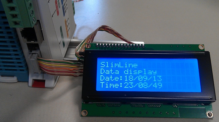
In questo programma viene istanziato il FB di gestione display, e viene gestita la visualizzazione dei messaggi. Alla attivazione è visualizzato un messaggio di benvenuto, poi dopo una temporizzazione si visualizza il messsaggio con data/ora.
LogicLab (Mdp238, ST_I2CLCDDisplay)
PROGRAM ST_I2CLCDDisplay
VAR
    PageNr : USINT; (* Page selector *)
    TimeBf : UDINT; (* Time buffer (uS) *)
    DTimeLocal : DATE_AND_TIME; (* Local Date/Time *)
    LDTValue : LDATE_AND_TIME; (* Long Date/Time value *)
    LCD : I2CLCDDisplay; (* LCD management FB *)
END_VAR

// *****************************************************************************
// PROGRAM "ST_I2CLCDDisplay"
// *****************************************************************************
// An example how to use the FB I2CLCDDisplay. It manages a 4*20 LCD display.
// -----------------------------------------------------------------------------

    // -------------------------------------------------------------------------
    // INITIALIZATION
    // -------------------------------------------------------------------------
    // Program initializations.

    IF (SysFirstLoop) THEN
        LCD.Backlight:=TRUE; //Backlight command
        LCD.I2CAddress:=16#3F; //LCD I2C address
        TimeBf:=SysGetSysTime(TRUE); //Time buffer (uS)
    END_IF;

    // Gestione blocco funzione display.

    LCD(Enable:=TRUE); //Gestione FB

    // -------------------------------------------------------------------------
    // MESSAGE DISPLAY
    // -------------------------------------------------------------------------
    // By using the "PageNr" variable some messages are displayed.

    CASE (PageNr) OF

        // ---------------------------------------------------------------------
        // WELCOME SCREEN
        // ---------------------------------------------------------------------
        // At system power up a welcome screen is displayed for 2 seconds.
        // +--------------------+
        // |I2CLCDDisplay       |
        // |Hello!              |
        // |                    |
        // |                    |
        // +--------------------+

        0:
        eTO_JUNK(Sysmemmove(ADR(LCD.DData[0]), ADR('I2CLCDDisplay       '), 20));
        eTO_JUNK(Sysmemmove(ADR(LCD.DData[1]), ADR('Hello!              '), 20));
        eTO_JUNK(Sysmemmove(ADR(LCD.DData[2]), ADR('                    '), 20));
        eTO_JUNK(Sysmemmove(ADR(LCD.DData[3]), ADR('                    '), 20));
        IF ((SysGetSysTime(TRUE)-TimeBf) > 2000000) THEN PageNr:=1; END_IF;

        // ---------------------------------------------------------------------
        // DATE/TIME MESSAGE
        // ---------------------------------------------------------------------
        // The date and time is displayed.
        // +--------------------+
        // |SlimLine            |
        // |Data display        |
        // |Date:xx/xx/xxxx     |
        // |Time:xx:xx:xx       |
        // +--------------------+

        1:
        DTimeLocal:=TO_DATE_AND_TIME(SysDateLocalize(SysDateGetS(), +1, DAYLIGHT_ZONE#DLZ_EUROPE)); //Local Date/Time (S)
        LDTValue:=TO_LDATE_AND_TIME(TO_ULINT(DTimeLocal)*ULINT#1000000000); //Local time on nanosecond

        eTO_JUNK(SysVsnprintf(ADR(LCD.DData[0]), SIZEOF(LCD.DData[0]), ADR('%s'), STRING_TYPE, ADR('SlimLine            ')));
        eTO_JUNK(SysVsnprintf(ADR(LCD.DData[1]), SIZEOF(LCD.DData[1]), ADR('%s'), STRING_TYPE, ADR('Data display        ')));
        eTO_JUNK(DateTimeFormat(LDTValue, ADR('^"Date:"d/m/Y"     "'), ADR(LCD.DData[2]), SIZEOF(LCD.DData[2])));
        eTO_JUNK(DateTimeFormat(LDTValue, ADR('^"Time:"H\:i\:s"       "'), ADR(LCD.DData[3]), SIZEOF(LCD.DData[3])));
    END_CASE;

// [End of file]